


Thermal Core SWaP: Why Size, Weight and Power Decide the Payload
Thermal camera cores are getting smaller, but the integration problem is not disappearing. It is moving. A core that looks compact on a datasheet can still force a larger housing, a heavier gimbal, a bigger battery or a more complicated cable route once the lens, interface board, connector and thermal path are added.
That is why experienced integrators talk about SWaP — size, weight and power — rather than detector size alone. For a UAV payload, a humanoid robot, a handheld observation device or a fixed security camera, the winning core is not the one with the smallest detector. It is the one whose installed envelope, mass and power draw fit the platform with the least compromise.
This article explains where the millimeters and watts actually go, how 12 µm pixel pitch changes the equation, and how to compare thermal cores on a like-for-like basis.
1. What SWaP Means for a Thermal Core
SWaP is shorthand for Size, Weight and Power. In a thermal core, each element has a different engineering meaning:
- Size — the installed envelope, including the lens, interface board, connector, mounting features and service clearance.
- Weight — the complete assembly, not the bare detector. The lens and housing usually dominate.
- Power — average and peak draw, including the detector, processing, interface board and lens motors.
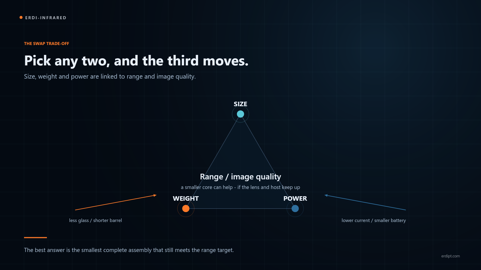
The three are linked. A smaller detector can allow a smaller lens, which reduces weight and improves gimbal balance. A lower-power core can run from a smaller battery, which reduces the payload further. In practice, SWaP is a chain of consequences, not three independent numbers.
2. Why the Detector Package Is Only Part of the Size
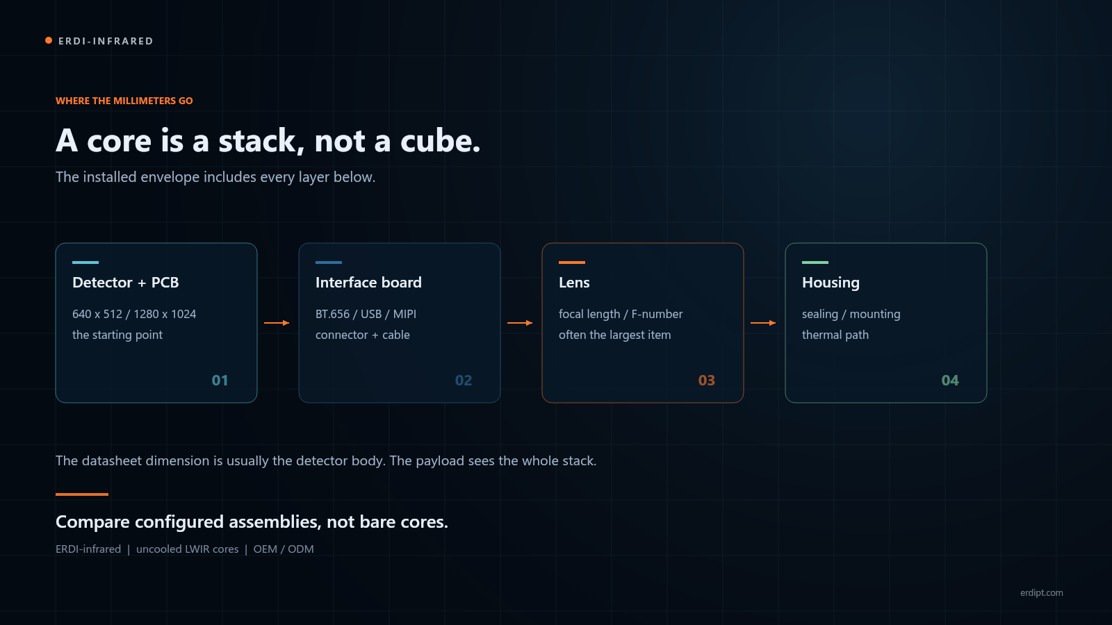
Start with the detector. A 640 × 512, 12 µm VOx core can sit in a body of about 26 × 26 × 25 mm. That number is real, but it is not the number a mechanical engineer can use for the payload envelope.
Four things are usually missing from that figure:
- The lens. A 19 mm lens adds length and diameter; a 100 mm lens adds much more.
- The interface board. BT.656, CameraLink, MIPI, USB and SDI paths do not use the same board or connector.
- The connector and cable. A right-angle connector still needs bend radius and service access.
- The mounting and thermal path. The core must transfer heat to the housing, not just sit inside it.
Therefore, compare the configured envelope, not the bare core. Ask for a drawing that shows the lens, board, connector and mounting holes together.
3. The Lens Is Often the Largest Contributor
In many thermal payloads, the lens is the largest and heaviest single item. This is not a defect; it is physics. A longer focal length needs a longer optical path and a larger front aperture to maintain sensitivity.
The practical consequences are easy to see:
- A wide-angle lens keeps the payload short and light, but gives less detail at distance.
- A long lens improves identification range, but adds length, mass and leverage on the gimbal.
- A fast lens (lower F-number) collects more infrared energy, but can increase diameter and cost.
For a UAV gimbal, the lens choice affects the balance point as much as the detector choice. A small core with a large lens can be harder to integrate than a slightly larger core with a compact lens. This is why the lens and core must be selected together.
4. The Interface Board Is the Hidden Volume
The interface is not a cable choice made after the mechanics are fixed. It is a board, a connector and sometimes a second PCB. A core that is 26 mm wide can become significantly wider once the interface board is fitted.
Different paths have different consequences:
- USB 3.0 is convenient for prototypes, but the connector and cable need space and strain relief.
- MIPI CSI-2 is compact, but the flex is short and the host needs the right lane configuration and driver.
- BT.656 / BT.1120 uses many pins and a parallel harness; it is compact at the board level but not always at the cable level.
- CameraLink adds a frame grabber and a larger connector, which is rarely the smallest option for one thermal channel.
Ask for the interface board dimensions, connector height and mounting holes. Then add the cable bend radius. The installed envelope is the only envelope that matters.
5. Power and Weight: Two Sides of the Same Budget
A 1280 × 1024 core can draw ≤1.2 W at 25 Hz; a 640 × 512 core runs from 5 V ± 0.5 V at 50 Hz. Those numbers look small, but they have a large effect on a portable system.
Power and weight are linked. A smaller battery saves weight, but only if the core and lens draw less. A lighter lens saves gimbal torque, but only if it still meets the range target. The two budgets must be calculated together.
5.1 Average vs peak
The datasheet figure is usually an average at a defined frame rate and temperature. Startup, shutter events and lens motors can draw more. Size the battery and regulator for the peak, not only the average.
5.2 Lens motors
A motorised focus or zoom lens adds power that is not part of the core datasheet. For a battery-powered payload, include the motor duty cycle in the energy budget.
5.3 Conversion losses
A 5 V core running from a 12 V or 24 V bus needs a converter. The converter has its own loss and heat. The same is true for a 2.7–5.3 V core running from a single-cell battery: the regulator must hold regulation across the full cell range.
5.4 The weight budget
Weight is not one number on a datasheet. It is the sum of the parts, and the distribution matters as much as the total.
| Component | Typical contribution | Why it matters |
|---|---|---|
| Lens | Often the largest single item | Glass mass, metal barrel and a long moment arm on the gimbal |
| Housing | High | Sealing, mounting, connector cut-outs and the thermal path |
| Interface board and connector | Medium | Board area, connector height, cable strain relief |
| Detector and processing PCB | Lower | Package, PCB and shielding |
5.5 Why bare-core weight misleads
A supplier may quote the weight of the bare core, or of the core with a short lens. Neither figure describes the assembly that bolts onto the gimbal. Ask for the weighed, configured assembly: core, lens, interface board, connector, bracket and fasteners.
For a first energy estimate, multiply average power by operating time and add margin for startup, motors and conversion losses. For example, 1.2 W for 4 hours is 4.8 Wh before margin; a 20–30% margin is a more realistic battery target. The exact number depends on duty cycle and temperature, so measure the real payload.
6. How 12 µm Pixel Pitch Changes the Equation
Pixel pitch is the distance between adjacent detector pixels. Moving from 17 µm to 12 µm allows more pixels in the same detector area, or the same pixel count in a smaller area. That is the first SWaP benefit.
The second benefit is optical. For the same field of view and resolution, a smaller pixel pitch can allow a shorter focal length, which can reduce lens length and diameter. However, this is not automatic. Diffraction, aperture size, lens design and image processing all set limits.
The correct conclusion is measured, not assumed: 12 µm pixel pitch creates options for smaller optics, but the final SWaP depends on the complete optical and mechanical design.
7. 640 × 512 vs 1280 × 1024: Same Lens, Different Core
With the same lens and field of view, a 1280 × 1024 core puts more pixels on the same target. That can improve recognition detail, but it also increases detector area, processing load and data rate. The core body is usually larger, and the interface board may need more bandwidth.
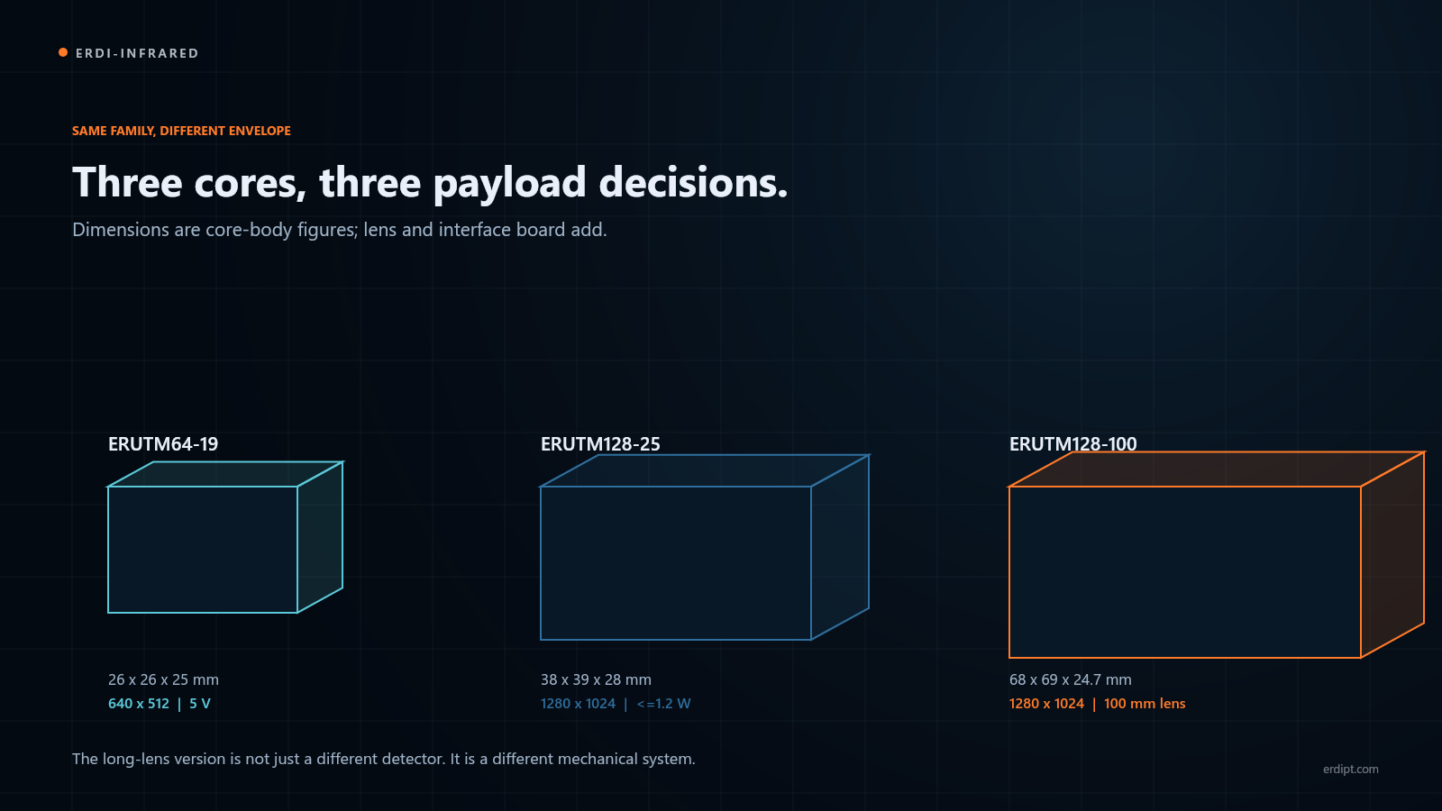
The table below compares three configurations from the ERUTM family. Dimensions are core-body figures; the lens and interface board add to them.
| Model | Resolution | Core body | Power / supply | Typical lens |
|---|---|---|---|---|
| ERUTM64-19 | 640 × 512 | 26 × 26 × 25 mm | 5 V ± 0.5 V, 50 Hz | 19 mm, 22.9° × 18.4° |
| ERUTM128-25 | 1280 × 1024 | 38 × 39 × 28 mm | 2.7–5.3 V, ≤1.2 W at 25 Hz | 25 mm, 34.2° × 27.6° |
| ERUTM128-100 | 1280 × 1024 | 68 × 69 × 24.7 mm | 2.7–5.3 V, ≤1.2 W at 25 Hz | 100 mm, 8.8° × 7.0° |
Note the pattern: the 1280 × 1024 core is larger, and the long-lens version is larger again. The difference is not only the detector; it is the optical and mechanical package that goes with it.
8. An Honest Note: What Small SWaP Does Not Solve
A smaller core is not automatically a better system. It does not:
- Increase the aperture. A small lens still collects less infrared energy than a large one.
- Beat atmospheric attenuation. Humidity, fog, dust and heat haze affect every core.
- Replace image processing. A high-resolution detector with poor processing can look worse than a well-tuned lower-resolution core.
- Remove the thermal path. A small, high-power-density core still needs a path to the housing.
- Fix a bad interface choice. The smallest core with the wrong cable and connector is still hard to integrate.
SWaP is a constraint, not a substitute for optical and system design. The right question is: what is the smallest complete assembly that still meets the range, image quality and environmental requirements?
9. A Practical SWaP Checklist for Integrators
Use this checklist before freezing the mechanical design:
- Installed envelope: core + lens + interface board + connector + cable bend radius.
- Mass: complete assembly, including lens, board, bracket and fasteners.
- Centre of gravity: especially for gimbals and head-mounted or robotic platforms.
- Power: average, peak, startup, shutter and lens-motor draw.
- Supply range: 5 V ± 0.5 V or 2.7–5.3 V, plus converter loss.
- Thermal path: how heat reaches the housing, and how the housing dissipates it.
- Interface: native or adapter board, connector height, cable length and host driver.
- Service access: can the lens be focused, the connector latched and the core replaced without removing the whole payload?
10. Where SWaP Matters Most
10.1 UAV payloads
Every gram on a gimbal affects flight time, balance and motor sizing. A compact 640 × 512 core with a 19 mm lens is often the best starting point; a 1280 × 1024 core with a longer lens is a deliberate trade for detail at range.
10.2 Humanoid and mobile robots
The head or neck of a robot has limited payload and power. A small core with USB 3.0 or MIPI CSI-2 can be integrated close to the compute unit, but the cable route and thermal path still need design attention.
10.3 Handheld observation
Battery life and balance matter more than a few millimetres. A 1.2 W core and a light lens can make the difference between a device that is carried all day and one that stays in the case.
10.4 Fixed security and industrial cameras
Size is less critical, but power, heat and lens range still matter. A larger core with a long lens can be the right choice when the camera is mains-powered and the target is far away.
11. Common Integration Mistakes
- Comparing bare core dimensions. The lens and interface board are part of the product.
- Forgetting the cable bend radius. A connector that fits in CAD may not fit in the housing.
- Budgeting average power only. Startup and lens motors can exceed the average.
- Assuming 12 µm doubles the range. Pixel pitch helps, but aperture, lens quality and atmosphere set the limit.
- Ignoring the thermal path. A small core can have a high power density; heat still has to leave.
- Choosing the interface last. The interface board can change the envelope and the schedule.
12. Frequently Asked Questions
How small is a 640 × 512 thermal core?
The ERUTM64-19 core body is 26 × 26 × 25 mm. The lens, interface board and connector add to that figure, so ask for the configured drawing.
Does a 1280 × 1024 core always weigh more?
Not always in isolation, but the complete assembly usually does. The detector, lens and interface board all tend to grow with resolution and bandwidth.
Does 12 µm pixel pitch improve detection range?
It can improve the optical package, but range is set by aperture, contrast, atmosphere and processing as well. Treat pixel pitch as one part of the chain, not a single number.
Can I use a smaller core with a long lens?
Yes, but check the lens mount, flange focal distance and centre of gravity. A long lens on a small core can create a mechanically unbalanced assembly.
What is the heaviest part of a thermal core?
It depends on the configuration. For long lenses, the lens and housing usually dominate; for short lenses, the housing and interface board can be significant. Ask for a weighed assembly.
Which interface is best for a compact payload?
It depends on the host. USB 3.0 is easiest to prototype; MIPI CSI-2 and BT.1120 are better for embedded designs; CameraLink suits machine vision. See our thermal core interface guide for the trade-offs.
13. Conclusion
Thermal core SWaP is a system property. The detector sets the starting point, but the lens, interface board, connector, housing and thermal path decide the installed envelope, mass and power draw.
When you compare cores, compare complete configurations. Ask for the installed drawing, the weighed assembly and the peak power. Then choose the smallest package that still meets the range and image-quality target.
For a first-pass comparison, use the thermal imaging module selection calculator. For the wider integration checklist, read Essential Considerations When Integrating an Infrared Thermal Imaging Module into Your System.
Related reading: 640 × 512 vs 1280 × 1024: Does Higher Resolution Actually Extend Detection Range? and Understanding Infrared Detector Pixel Pitch.