


Uncooled LWIR Cores: A Complete Selection Guide for OEM Integrators
Most uncooled LWIR core projects fail for reasons that have nothing to do with the detector. The core was chosen from a headline resolution figure, the lens was specified for range, the interface was assumed to be “just USB”, and six months later the payload is overweight, latency-bound and cannot recognise what it was bought to recognise.
This guide walks through the decisions in the order they actually constrain each other, and gives you the numbers to argue with. It follows the uncooled LWIR core decision end to end: target and range, detector and lens, interface, environment and radiometry. Every range figure in this article was calculated with the same formulae used in our thermal module selection calculator — field of view, IFOV, pixels on target, then the Johnson criteria for detection, recognition and identification.
1. Start with the target, not the detector
Before any datasheet is opened, write down four things:
- What the observer must decide — detect something, classify it, or describe it.
- At what range, and from what platform (handheld, gimbal, fixed mast, moving vehicle).
- How much area must be covered at once — a corridor, a perimeter, a 2 km stretch of coastline.
- What the target’s thermal contrast is — a running engine at dawn is easy; a cold, still person in wet clothing at midday is not.
The first two decide the pixel count on target. The third decides the field of view. The fourth decides whether your chosen sensitivity is honest. Everything else is engineering.
The Johnson criteria, briefly
The classical Johnson criteria say that a target’s critical dimension must span roughly:
- 2 pixels to detect it,
- 8 pixels to recognise it (person / vehicle / animal),
- 16 pixels to identify it (describe it in useful detail).
These are ideal-observer figures measured under good contrast. They are a planning tool, not a promise. Real range shrinks with haze, humidity, low ΔT, motion, poor focus and display quality — which is why serious spec sheets quote ranges with the conditions attached.
Critical dimensions of common targets
| Target | Critical dimension | Note |
|---|---|---|
| Standing adult | 0.5 m | NATO-style reference target |
| Person with equipment / crouching | 0.75 m | Use when the target may be partly concealed |
| Small multirotor drone | 0.3 m | Airframe only |
| Light vehicle / pickup | 2.3 m | Width across the vehicle |
| Shipping container (20 ft) | 2.4 m | Height |
| Small boat | 2–3 m | Beam, depends on hull |
| Hot spot on a PCB | 5–20 mm | Needs macro optics, not long range |
2. What an uncooled LWIR core actually is
An uncooled long-wave infrared core images the 8–14 µm band using a microbolometer array: a grid of tiny thermally isolated pixels (amorphous silicon or vanadium oxide) whose electrical resistance changes as absorbed infrared radiation warms them. A read-out integrated circuit samples that change, and the core turns it into a video stream.
Three consequences matter commercially:
- No cryogenic cooler. That is why uncooled cores are smaller, cheaper, quieter and far more reliable than cooled MWIR engines — and why they dominate UAV, security and industrial volume.
- **They measure temperature difference, not absolute temperature.** Absolute radiometry is possible, but it has to be engineered (Section 3.5).
- Everything is a compromise between sensitivity and speed. Smaller pixels and faster shutters both cost you signal.
Typical modern cores run TEC-less (no thermoelectric cooler) with digital compensation of the substrate temperature drift, which is what brought power consumption under a watt in the small formats.
3. The seven specifications that decide your design
Every specification below interacts with the others: change one and the uncooled LWIR core you can actually use changes with it.
3.1 Resolution and pixel pitch
Resolution (for example 640 × 512) tells you how many pixels you have. Pixel pitch (12 µm, 17 µm) tells you how large each one is physically — and it, not the resolution, determines the sensor’s size, the lens you need and the instantaneous field of view.
- A 640 × 512 array at 12 µm is 7.68 × 6.14 mm.
- The same array at 17 µm is 10.88 × 8.70 mm.
The smaller-pitch sensor lets you use a shorter, smaller, cheaper lens for the same field of view — which is exactly why the industry moved from 17 µm to 12 µm, and is now moving to 10 µm and below. But smaller pixels collect less radiation per pixel, so sensitivity has to be maintained by better absorption structures and lower-noise read-out; check NETD at the same F-number before assuming a smaller pitch is free.
3.2 Sensitivity: NETD and what the number hides
NETD (noise equivalent temperature difference) is the temperature difference that produces a signal equal to the noise — typically quoted in millikelvin, e.g. “< 40 mK”. Two rules:
- Always compare at the same F-number and frame rate. A 50 mK figure at F/1.4 is not comparable with a 30 mK figure at F/1.0.
- NETD is measured at a laboratory target temperature and spatial frequency. A core that looks excellent on a blackbody can look flat in the field if the image pipeline is weak.
For long-range recognition of low-contrast targets, NETD matters more than another million pixels. For wide-area surveillance of warm vehicles, it rarely limits you.
3.3 The lens: where most of the money and most of the range lives
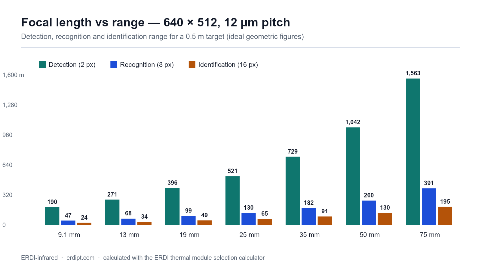
At a fixed detector, range scales linearly with focal length and field of view shrinks in the same proportion. Table 1 shows the trade for a 640 × 512 / 12 µm core with a 0.5 m target.
Table 1 — 640 × 512, 12 µm pitch: how focal length changes field of view and range (human target, 0.5 m critical dimension)
| Focal length | HFOV | VFOV | IFOV | FOV width at 100 m | Detection (2 px) | Recognition (8 px) | Identification (16 px) |
|---|---|---|---|---|---|---|---|
| 9.1 mm | 45.8° | 37.3° | 1.32 mrad | 84.4 m | 190 m | 47 m | 24 m |
| 13 mm | 32.9° | 26.6° | 0.92 mrad | 59.1 m | 271 m | 68 m | 34 m |
| 19 mm | 22.9° | 18.4° | 0.63 mrad | 40.4 m | 396 m | 99 m | 49 m |
| 25 mm | 17.5° | 14.0° | 0.48 mrad | 30.7 m | 521 m | 130 m | 65 m |
| 35 mm | 12.5° | 10.0° | 0.34 mrad | 21.9 m | 729 m | 182 m | 91 m |
| 50 mm | 8.8° | 7.0° | 0.24 mrad | 15.4 m | 1,042 m | 260 m | 130 m |
| 75 mm | 5.9° | 4.7° | 0.16 mrad | 10.2 m | 1,563 m | 391 m | 195 m |
Lens choices that matter as much as focal length:
- F-number. A faster lens (lower F/#) puts more energy on each pixel and improves effective sensitivity, at the cost of size, weight, cost and depth of focus. F/1.0 is common on compact cores; F/1.2–1.4 on larger apertures.
- Material. Germanium has excellent transmission and a high refractive index, but it is expensive, heavy and thermally unstable without athermalisation. Moulded chalcogenide glasses allow athermalised designs and lower unit cost at volume.
- Athermalisation. Focus must stay stable from −40 °C to +70 °C. Passive athermalisation (mechanical compensation) is preferable to motorised focus for most payloads — but motorised focus is worth it if you need to work across a huge range span.
- Mount and sealing. Lens-to-detector alignment tolerances are in tens of microns; a mount that survives vibration is not optional on gimbals.
3.4 Frame rate, interface and latency
| Interface | Typical use | Watch out for |
|---|---|---|
| Analogue (PAL/NTSC) | Legacy retrofits, simple displays | No metadata, limited resolution fidelity |
| BT.656 / ITU-R BT.656 | Compact cores, embedded SoCs | Fixed timing, needs a real frame buffer |
| LVDS / Camera Link | High-rate, machine vision | Cable length and EMI discipline |
| USB (UVC) | Bench work, industrial PCs, quick prototypes | Bandwidth sharing, latency jitter, cable limits |
| MIPI CSI-2 | Embedded boards (Jetson, Raspberry Pi class) | Driver and ISP integration effort |
| Gigabit Ethernet / GigE Vision | Fixed installations, multi-camera | Power over Ethernet budget, switch behaviour |
Two integration realities:
- Latency, not resolution, breaks tracking loops. Ask for end-to-end latency (sensor → video out), not just frame rate. A 30 Hz stream with 120 ms of processing latency is unusable for a fast gimbal.
- Bandwidth is a budget. 640 × 512 × 16 bit × 50 Hz is already ~26 MB/s before overhead.
3.5 Radiometry: imaging versus measuring
If the customer needs numbers (°C) rather than pictures, specify it now:
- Radiometric cores are factory-calibrated against blackbodies and output temperature; accuracy is typically quoted as ±2 °C or ±2 % of reading within a stated range.
- Accuracy depends on the scene: emissivity, distance, atmospheric transmission and reflected radiation must be compensated — most SDKs expose those parameters, few integrators use them.
- Drift. Shutter-based non-uniformity correction (NUC) re-references the array periodically, which is accurate but freezes the image for a frame; shutterless designs avoid the freeze at the cost of more careful compensation. For temperature measurement, keep the shutter.
3.6 Mechanical, environmental and power envelope
- Operating temperature (−40 °C to +70 °C is a common industrial window), storage, and cooldown/warm-up time to specification.
- Ingress protection and sealing for the assembly, not just the core: an IP67 housing with an unsealed lens thread still fogs.
- Shock and vibration to a defined standard if the platform moves; ask for the test report, not the claim.
- Power: small uncooled cores run from a few hundred milliwatts; add the lens motor, heater and processing board before you size the battery.
3.7 Software, SDK and the image pipeline
The core’s raw image is not the image your customer sees. Ask what the pipeline does and whether you can control it:
- Non-uniformity correction and bad-pixel replacement — mandatory, and the quality is visible immediately.
- AGC / DDE (automatic gain control, digital detail enhancement) — this is why two cores with identical detectors look completely different.
- Palettes, isotherms, digital zoom, spot/line temperature tools — the customer-facing features.
- Tracking and detection — often a separate module; if the core exposes a metadata channel, your tracker can be simpler and cheaper.
- SDK quality: documented registers, sample code for your OS, and whether the vendor will answer a question in week three of integration.
4. Reading a datasheet without being flattered
Three comparisons expose most marketing:
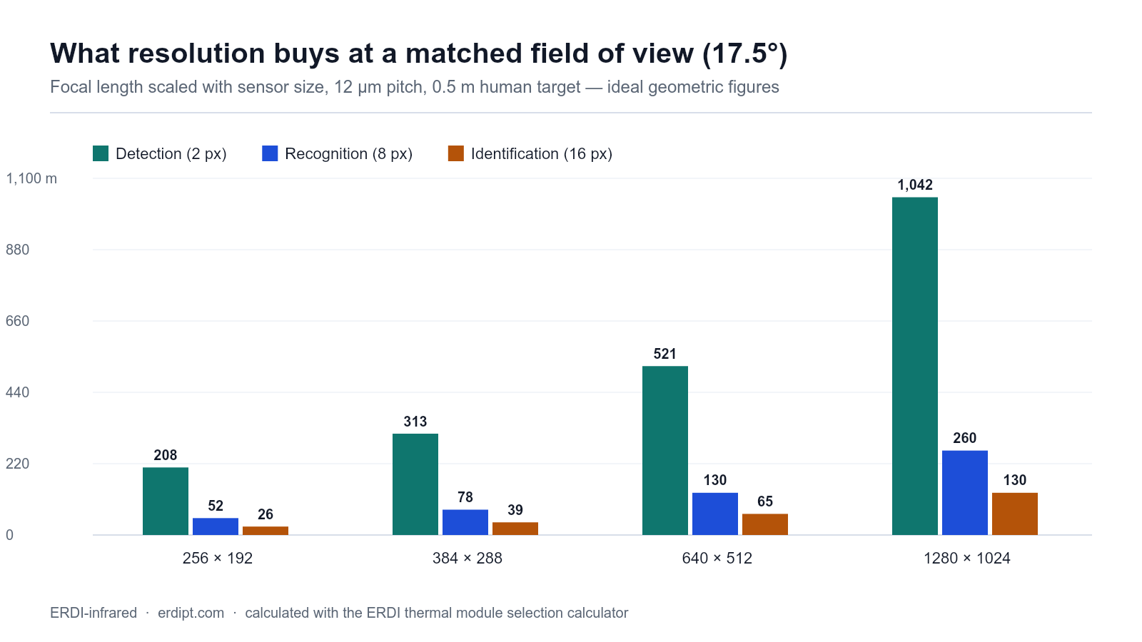
- Normalise to the same field of view. At equal field of view, range is set by pixels on target, so the higher-resolution core with a proportionally longer lens wins. Table 2 does the arithmetic at 17.5° horizontal.
Table 2 — matched field of view (17.5° horizontal), 12 µm pitch: what a bigger detector actually buys
| Detector | Focal length for 17.5° HFOV | IFOV | Detection (human 0.5 m) | Recognition | Identification | Detection (vehicle 2.3 m) |
|---|---|---|---|---|---|---|
| 256 × 192 | 10.0 mm | 1.20 mrad | 208 m | 52 m | 26 m | 958 m |
| 384 × 288 | 15.0 mm | 0.80 mrad | 313 m | 78 m | 39 m | 1,438 m |
| 640 × 512 | 25.0 mm | 0.48 mrad | 521 m | 130 m | 65 m | 2,396 m |
| 1280 × 1024 | 50.0 mm | 0.24 mrad | 1,042 m | 260 m | 130 m | 4,792 m |
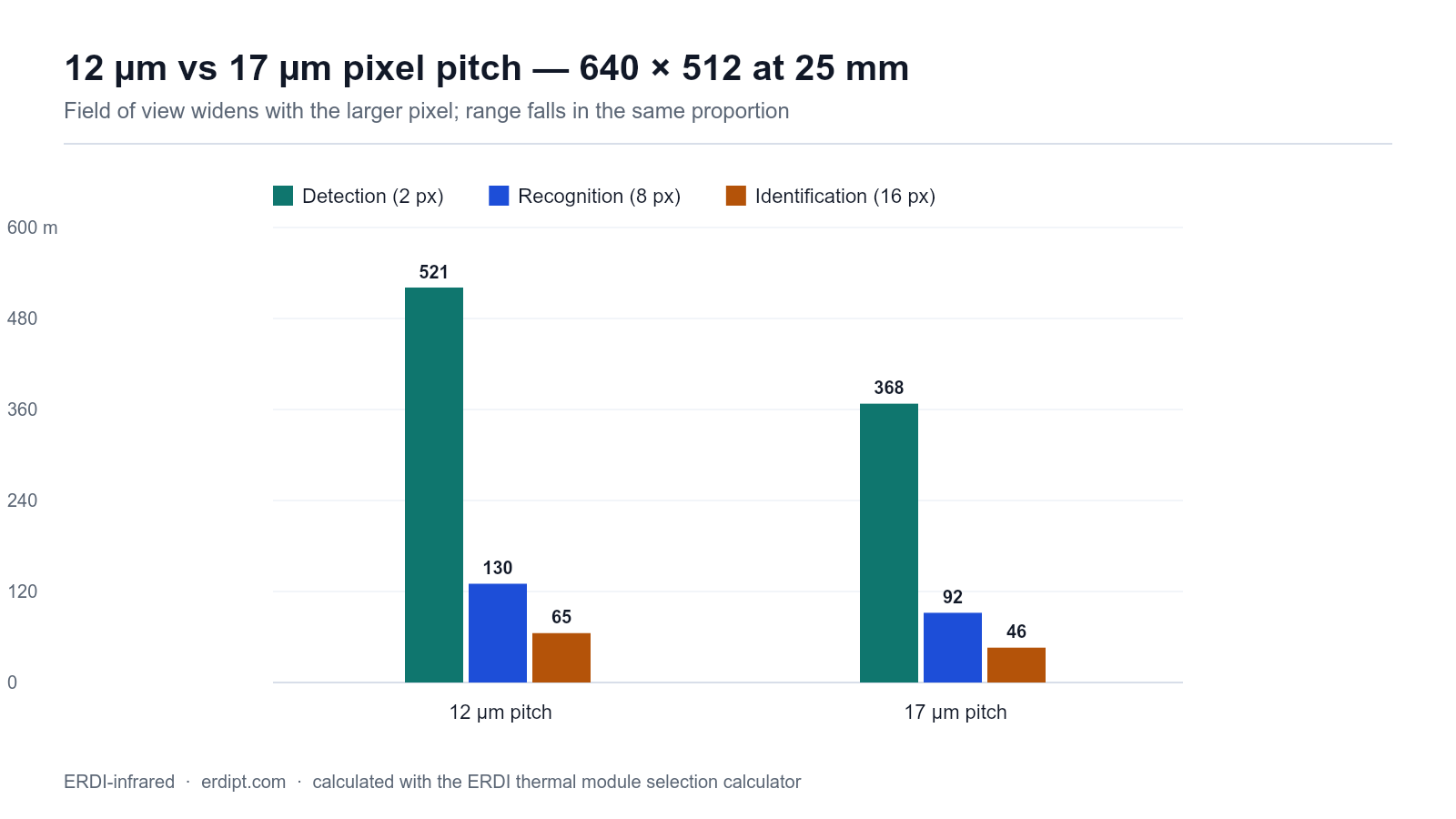
- Compare pixel pitches at the same focal length, not at the same field of view. Table 3 shows the honest trade: the 17 µm array sees wider, the 12 µm array sees further with the same glass.
Table 3 — 640 × 512 at 25 mm: 12 µm vs 17 µm pitch
| Pixel pitch | Sensor size | HFOV | IFOV | Detection (human) | Recognition (human) |
|---|---|---|---|---|---|
| 12 µm | 7.68 × 6.14 mm | 17.5° | 0.48 mrad | 521 m | 130 m |
| 17 µm | 10.88 × 8.70 mm | 24.6° | 0.68 mrad | 368 m | 92 m |
- Ask which conditions the range figures assume. A range quoted at “detection” with no ΔT, no atmospheric model and no F-number is a decoration, not a specification.
5. Matching the core to the application
The same uncooled LWIR core behaves very differently across applications, so match it to the mission rather than to a specification table.
| Application | What usually wins | What usually traps people |
|---|---|---|
| UAV / drone payload | Small pitch (12 µm) and 640 × 512 or higher, wide-to-medium lens, low latency, < 500 g total | Choosing range over weight; ignoring gimbal latency; no athermalisation |
| Perimeter & critical infrastructure | 384 × 288 or 640 × 512, medium lens, 25–30 Hz, GigE, analytics metadata | Underestimating detection software cost; single-camera coverage assumptions |
| Industrial inspection | Radiometric 640 × 512 with macro or mid lens, high frame rate, good SDK | Non-radiometric core “upgraded” later — usually a redesign |
| Fire detection | Wide field of view, fast NUC, high dynamic range (fire is very hot, background is not) | Saturation and blooming near the fire front |
| Robotics & AGV | Compact core, MIPI/USB, low power, shutterless if possible | Latency and mechanical shock |
| Marine observation | 640 × 512, stabilised mounting, 25 µm-class sensitivity or better, salt-fog rated housing | Humidity fogging and corrosion, not optics |
| Weapon sights | 640 × 512, ruggedised, parallax-free integration, daylight channel | Weight, eye relief, reticle alignment — see our thermal imaging sights range |
6. The eight integration mistakes we see most
- Specifying range without field of view. A 50 mm lens on a search payload is a telescope: excellent for the one target you already found, useless for finding it.
- Forgetting atmospheric and ΔT de-rating. Apply 0.6–0.8 of the ideal geometric range for real conditions — the calculator does this with a selectable factor.
- Treating NETD as comparable across F-numbers. It is not.
- Ignoring latency. Measure it; do not assume it.
- Underestimating the image pipeline. The cheapest place to buy image quality is a vendor whose AGC/NUC is already good.
- Bolting a lens onto a core without athermalisation and then wondering why focus drifts on a cold morning.
- Assuming thermal behaves like visible. It is a low-contrast, low-texture, high-dynamic-range signal; your visible-band processing habits will fail on it.
- Treating radiometry as a firmware switch. It is a calibration chain: blackbody, emissivity, distance, atmosphere.
7. Testing and acceptance before you commit to volume
- Bench: NETD spot check at a known ΔT, bad-pixel count, image uniformity after NUC, warm-up drift over 60 minutes.
- Range: a target board at a known ΔT and distance; log detection, recognition and identification ranges, and compare with the calculated figures. Do this twice — once at midday, once at dawn.
- Environmental: temperature soak at both ends, vibration to the platform’s standard, and an ingress check on the finished assembly, not the bare core.
- Integration: latency measurement, power draw at start-up (surge) and steady state, and a full-day soak with your own processing board.
- Documentation: SDK version, register map, calibration certificate and the environmental report — ask before you order, because afterwards you will be told it is “not normally provided”.
8. Cost, lead time and lifecycle
- Silicon economics: smaller pitch means more dies per wafer, which is the main reason 12 µm cores now cost what 17 µm cores did — not a temporary discount.
- Lens economics: above roughly 50 mm, the lens can cost more than the core. Decide early whether the range requirement justifies it.
- Volume and MOQ: sample pricing is not production pricing; ask for the curve, not the number.
- Second source and longevity: for a product with a five-year life, ask how long the core, lens and connectors will be available, and what the migration path looks like. A pin-compatible family across formats is worth real money later.
9. Compliance and documentation
Thermal imaging hardware is dual-use technology in many jurisdictions, and classification depends on resolution and frame rate as well as on the end use. Two practical steps: ask your supplier which classification applies to the specific configuration you are buying, and confirm what end-user and export documentation they provide. Do this before you design the core into a product you intend to export — not after the first order.
10. A pre-commitment checklist
- [ ] Observer task defined: detect / recognise / identify, per target type
- [ ] Required range and required field of view, written down together
- [ ] Target critical dimension and expected ΔT recorded
- [ ] Detector format chosen to satisfy both, not just one
- [ ] Lens focal length, F-number, material and athermalisation specified
- [ ] Interface, frame rate and latency requirements agreed with the processing team
- [ ] Radiometric or imaging-only decision made and costed
- [ ] Environmental envelope, mounting and sealing defined
- [ ] Image pipeline features and SDK quality assessed on a sample unit
- [ ] Range test performed with your own eyes, twice, in different conditions
- [ ] Volume price, lead time, second source and lifecycle answer in writing
- [ ] Classification and export documentation clarified
11. Frequently asked questions
Is 640 × 512 enough, or do I need 1280 × 1024?
If your field of view is fixed and you need more range, the higher format gives you roughly double the pixels on target and therefore roughly double the range (Table 2). If you need wide-area coverage at moderate range, 640 × 512 with a good lens and pipeline is usually the better economic choice. Decide from the two numbers — range and field of view — not from the format alone.
Should I choose 12 µm or 17 µm pixels?
For new designs, 12 µm: it gives the same field of view with a smaller, lighter, cheaper lens. Choose 17 µm when you need maximum signal per pixel at a low F-number, or when you are reusing legacy optics.
Do I need a shutter?
For imaging, a shutterless core removes the periodic freeze and improves mechanical reliability. For radiometric measurement, keep the shutter: it is part of the calibration chain.
Why are the quoted ranges so much longer than what I see in the field?
Because quoted ranges are geometric and idealised. Apply a factor of 0.6–0.8 for haze, humidity and low thermal contrast, then subtract for motion and display quality. Our selection calculator shows both columns side by side so the difference is explicit.
Can one core do both wide search and long-range identification?
Not well. This is why dual-channel and dual-FOV payloads exist, and why so many UAV gimbals carry a 9–13 mm channel next to a 35–50 mm one.
12. Work out your own configuration
Use the thermal imaging module selection calculator to turn your target, lens and detector into field of view, pixels on target and DRI ranges — then send us the result with your platform and annual quantity, and our engineers will reply with a configuration proposal.
If you are starting from a payload requirement rather than a detector, these pages go deeper on the application side: thermal imaging for UAV payloads, security and surveillance and the drone thermal module buyer’s guide. For background on why pixel size changes everything, see why pixel pitch matters.