

MIPI, USB, BT.656 or CameraLink? Choosing the Right Interface for an Uncooled LWIR Core
Most thermal-core projects start with resolution and lens. However, the interface often waits until the carrier board is almost finished. Then it becomes the decision that sets the schedule. A thermal core interface is more than a connector. It defines the video path, the control path, cable length, the power budget, host software and the mechanical envelope. If you choose it late, a good detector can sit idle while you wait for a frame grabber.
This guide compares the four interface families that matter most for an uncooled LWIR core: MIPI CSI-2, USB 3.0, BT.656/BT.1120 and CameraLink. It also explains where SDI, HDMI and GigE fit as expansion paths. Therefore, the aim is simple: help you make a choice that holds up in production, not just on a bench.
Why the interface is a system decision
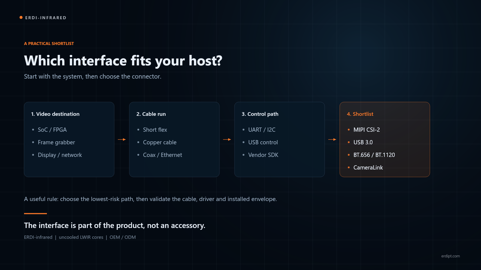
Four questions decide the interface more reliably than a product brochure. First, where does the video go? A display, a SoC, an FPGA, a frame grabber or a network. Second, who controls the core? The same host, a separate microcontroller, or a factory test fixture. Third, how far and through what? A flex inside a gimbal, a cable through a mast, or a network run. Finally, what can the mechanics and power budget afford? Connector height, board area, cable bend radius and additional watts.
In practice, one detector can use different interface boards. However, the host consequences are not interchangeable. A USB 3.0 link is easy on a bench, but it can be the wrong choice inside a sealed payload. A MIPI link saves space, but it can add weeks of driver work. Therefore, choose the lowest-risk path that meets the product. Do not choose the highest-bandwidth path just because the datasheet offers it.
The four main paths at a glance
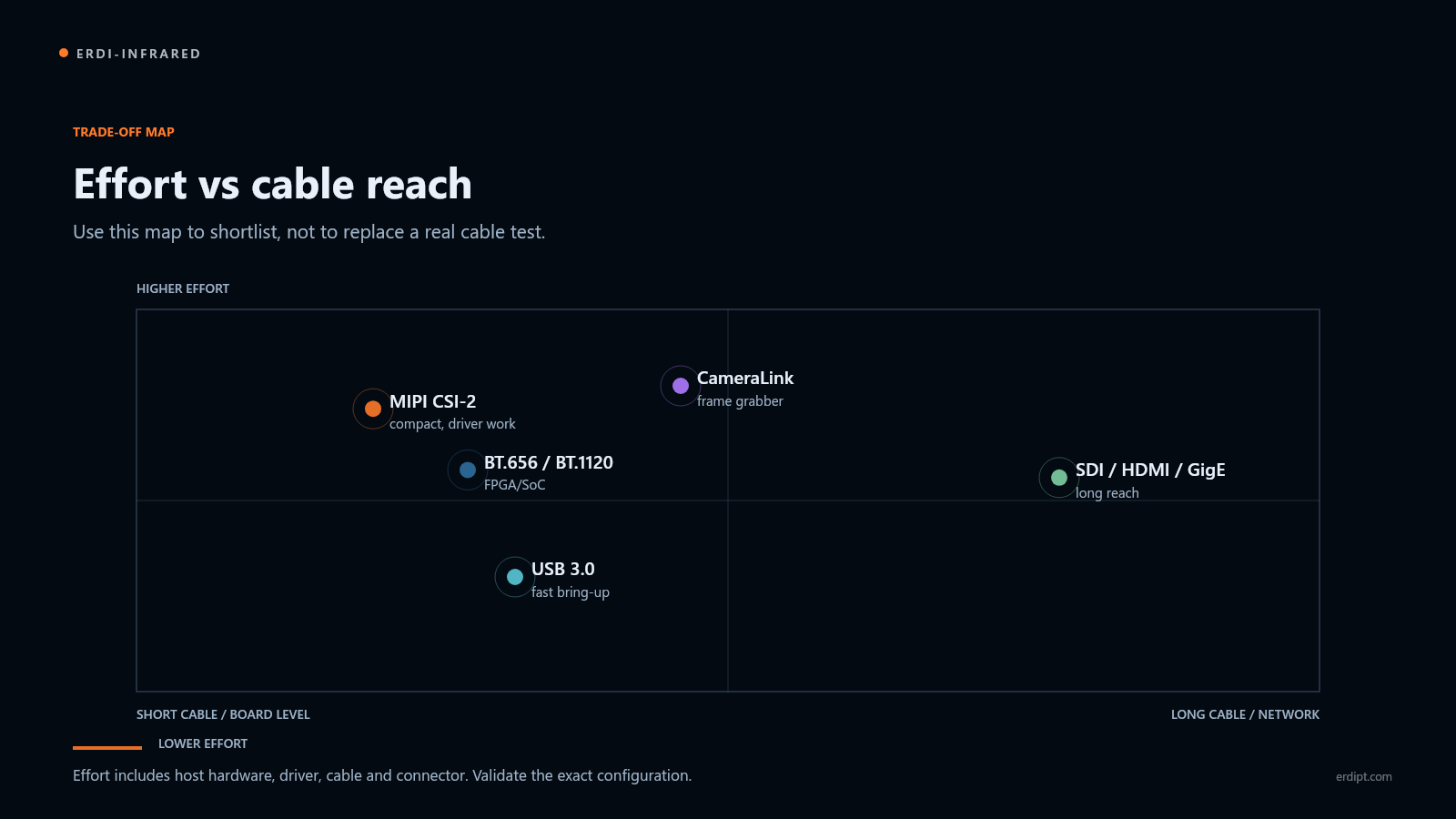
First, the table below summarizes the trade-offs. Use it to shortlist two paths, then validate the details with the supplier.
| Interface | Best fit | Host side | Cable / distance | Main trade-off |
|---|---|---|---|---|
| MIPI CSI-2 | Compact embedded vision, SoCs and FPGAs | CSI-2 receiver and a Linux driver | Short flex, typically tens of centimetres | Smallest and lowest latency, but the least forgiving to integrate |
| USB 3.0 | Prototypes, x86 boxes, Raspberry Pi 5, portable systems | USB 3.0 host controller; vendor SDK or UVC | A few metres with passive cables; extenders for more | Fastest to bring up, but higher latency and less deterministic than a parallel bus |
| BT.656 / BT.1120 | FPGA/SoC designs that need deterministic timing | Parallel video capture port | Short PCB traces or a short shielded cable | Simple protocol, but many pins and careful signal integrity |
| CameraLink | Machine vision, industrial inspection, frame grabbers | CameraLink frame grabber | A few metres with the specified cable | High bandwidth and maturity, but an extra card and connector cost |
| SDI / HDMI / GigE | Long cable, monitoring, networked systems | SDI receiver, HDMI input or NIC | SDI: long coax; HDMI: short; GigE: up to 100 m per segment | Convenient distance, but more latency, compression or conversion |
In practice, most teams shortlist USB 3.0 for a prototype and then move to MIPI, BT.1120 or CameraLink for production. That is a sensible sequence, as long as you design the production carrier board early enough.
MIPI CSI-2 and MIPI DSI: similar names, different jobs
“MIPI” is a family of interfaces, not one interface. MIPI CSI-2 is the camera serial interface. It carries image data from a sensor or core into a host SoC or FPGA. MIPI DSI is a display serial interface. It carries image data out to a screen. They can share a connector family and a lane count, but they are not interchangeable.
Therefore, ask which port the core implements and in which direction. A core that provides MIPI DSI may be intended to drive a local display, not to stream into a host processor. If the host only has a DSI output, it is not a camera input.
In practice, MIPI CSI-2 is compact, power-efficient and well matched to embedded SoCs. However, the costs are real. Lane count and clock must match the host. The flex is short. The Linux driver or ISP pipeline has to be ported. For example, a Raspberry Pi 5 usually takes the USB 3.0 path with less risk. A MIPI CSI-2 camera needs the right lane configuration, device tree and driver. As a result, validate the combination before design freeze.
USB 3.0: the lowest-friction path, with limits
For most teams, USB 3.0 is the interface they try first. It is available on almost every development board and PC. It supports a few metres of passive cable, and it can power the core from the host. Therefore, it removes an entire board bring-up phase for a prototype, a trade-show demo or a short-run product.
However, “USB” does not always mean “plug and play”. There are two different USB camera models:
- UVC (USB Video Class) — the host sees a standard camera, and the operating system supplies the driver. This is fast to test, but the core’s control functions and raw formats may be limited.
- Vendor SDK — the host installs the supplier’s driver and SDK. This gives more control and raw access, but the software becomes part of your integration and must be maintained.
Therefore, ask which model applies before design freeze. USB 3.0 also has higher and less deterministic latency than a parallel or MIPI link. A passive cable run is not unlimited. For a gimbal or a sealed payload, the connector and cable bend radius can matter as much as the data rate.
BT.656 and BT.1120: parallel video for embedded designs
BT.656 and BT.1120 are parallel video buses. BT.656 is the older 8-bit SD-era interface. BT.1120 is a 16-bit HD-oriented interface. Their advantage is determinism. The timing travels with the data, there is no packetization, and an FPGA or SoC can capture frames with a small, predictable pipeline.
However, their cost is physical. A parallel bus uses many pins, and it needs careful length matching. It works best over short PCB traces or a short shielded cable. Therefore, it fits inside a camera housing or a dedicated payload board, not a long vehicle cable. There is also no hot-plug or enumeration layer. You must design the host for the core, not the other way round.
CameraLink: machine-vision bandwidth
In practice, CameraLink is the industrial machine-vision standard. It packages parallel video and control signals into a shielded connector. A frame grabber in the host receives the data. Base, Medium and Full configurations trade connector size and cable count for bandwidth. The standard is mature, deterministic and well supported by industrial vision software.
For example, CameraLink makes sense when the rest of the system already uses it, or when the host needs a frame grabber for multiple cameras and hard real-time capture. However, it is rarely the cheapest or smallest option for one thermal channel. The frame grabber, cable and connector all add cost and volume.
SDI, HDMI and GigE: expansion paths
By contrast, SDI, HDMI and GigE are usually expansion paths. An interface board or an external converter adds them; the detector does not implement them directly.
- SDI uses coax cable. It supports long runs and fits broadcast or professional video infrastructure. This is a good choice for a mast or a fixed installation where the camera is far from the monitor.
- HDMI is short and consumer-grade. It works for a local monitor or a demo, but it is not the first choice for a rugged or long-cable system.
- GigE uses standard Ethernet. It supports up to 100 m per segment, and it is easy to route through a network. However, packetization adds latency and jitter. GigE Vision is a better fit than a raw stream when the host expects a standard.
Therefore, an expansion interface is still an interface choice. It adds a board, a connector, power and often a converter. Therefore, include it in the mechanical and thermal budget from the start.
How ERDI implements the interface
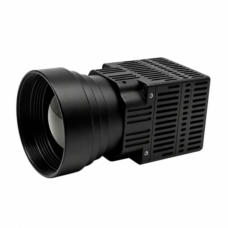
ERDI-infrared builds uncooled LWIR cores as bare modules. Therefore, the interface is part of the configuration, not an afterthought.
The ERUTM64 series (640 × 512, 12 µm, 50 Hz) uses a replaceable interface board. Available video paths include BT.656, CameraLink, MIPI, USB and SDI. In addition, UART × 2 and RS232 × 2 handle control. The core runs from 5 V ± 0.5 V and measures 26 × 26 × 25 mm. The interface board and connector add to that envelope. The ERUTM64-19 is the 19 mm lens version, a balanced 640 × 512 configuration for general integration.
The ERUTM128 series (1280 × 1024, 12 µm, 25/30/50 Hz) has a different native set: DVP16, BT.1120, USB 3.0 and MIPI-DSI-4LANE. It expands to USB 3.0, SDI, HDMI, GigE, CameraLink, VPC and MIPI-CSI-2LANE. It runs from 2.7–5.3 V and draws ≤1.2 W at 25 Hz. The fixed-lens versions measure 38 × 39 × 28 mm; the 50 mm and motorized/continuous-zoom versions use a 68 × 69 × 24.7 mm body. A Windows/Linux SDK is available for the USB 3.0 path. See the ERUTM128-25 and ERUTM128-35 for the wide and balanced lens options.
However, two details matter. First, native and expandable are not the same. A native port is on the core or its standard board. An expandable port needs an additional board, and it may change the envelope. Second, the MIPI-DSI port on the 128 series is a display-side interface. If the host needs a camera input, ask for the MIPI-CSI-2LANE expansion path explicitly.
Seven questions to ask before you choose
First, before you commit, ask these seven questions. They catch most of the expensive surprises.
- Is the interface native or an adapter board? Ask for the board dimensions, connector height and mounting holes. This matters because the installed envelope is larger than the bare core.
- What is the video path, and what is the control path? Video does not imply control. You must specify UART, I2C or USB control separately.
- What exactly does the host support? Check lane count, clock, USB controller, frame grabber and operating system. “Linux” is not a driver.
- How long is the cable, and what is around it? Motors, radios and switching regulators are the usual sources of EMI on a gimbal. Therefore, test the real cable, not a bench lead.
- What is the power budget? Add the core, interface board, lens motors and focus/zoom electronics. A 1.2 W core can become a 3 W assembly.
- What is the mechanical envelope after you fit the interface? The core datasheet dimension is not the installed dimension. Check bend radius and service access too.
- What SDK, documentation and lifecycle support come with it? Ask for the integration manual, register map, sample code and change policy. This is especially important for a product with a multi-year life.
Common integration mistakes
In practice, here are the mistakes we see most often. Each one is cheaper to fix before the carrier board is fabricated.
- Using USB 2.0 bandwidth for a 1280 × 1024 stream. Check the raw data rate, not just the frame rate.
- Confusing MIPI DSI with MIPI CSI-2. One drives a display; the other accepts a camera.
- Running a parallel bus too far. BT.656 and BT.1120 are not long-cable interfaces.
- Forgetting the frame grabber. CameraLink is not a USB-style host connection.
- Ignoring the control channel. A video link alone cannot set integration time, gain, palette or NUC.
- Budgeting only the detector. The interface board, lens motors and cable all draw power and generate heat.
- Assuming UVC. A vendor SDK can be the right choice, but it is a software dependency, not a free driver.
Frequently asked questions
Can I connect the core directly to a Raspberry Pi 5?
Therefore, USB 3.0 is the lowest-risk path on a Raspberry Pi 5. MIPI CSI-2 is possible only if the core’s lane configuration, clock and Linux driver match the host. Therefore, verify a working combination before design freeze.
Is USB always plug-and-play?
No. For example, some USB cores present as UVC cameras; others require a vendor SDK. Ask which model applies, and whether raw data and full control are available in each.
Which interface is best for a UAV payload?
In practice, it depends on the payload architecture. USB 3.0 is convenient for a prototype or a small payload. BT.1120 or MIPI CSI-2 is a better fit for an embedded SoC or FPGA. SDI or GigE makes sense when the camera is far from the processor.
How long can the cable be?
For example, MIPI is the shortest, typically tens of centimetres on a flex. USB 3.0 is good for a few metres with a passive cable. CameraLink and BT.656/BT.1120 are short-cable interfaces. SDI and GigE are the long-distance options. Treat these as starting points, then validate the actual cable and connector.
Do I need a frame grabber?
In contrast, CameraLink needs one. USB 3.0, MIPI CSI-2 and BT.656/BT.1120 use a host controller, a CSI receiver or an FPGA capture port instead.
Can I use MIPI DSI to capture video?
No. Instead, DSI is a display output. For a camera input, ask for MIPI CSI-2.
Summary
In summary, the best thermal core interface is the one your host can support without a science project. First, define the video path. Then define the control path. Next, measure the cable and power budget. Finally, choose the connector. If you are weighing MIPI, USB 3.0, BT.656/BT.1120 or CameraLink for an uncooled LWIR core, send us the host platform, the cable length and the power budget. We will recommend the lowest-risk configuration for the ERUTM64 or ERUTM128 series.
For a first-pass lens and range check, use the thermal imaging module selection calculator. For the wider integration checklist, read Essential Considerations When Integrating an Infrared Thermal Imaging Module into Your System.
Related reading: 640 × 512 vs 1280 × 1024: Does Higher Resolution Actually Extend Detection Range? and How to Choose the Right Thermal Imaging Module for a Drone.