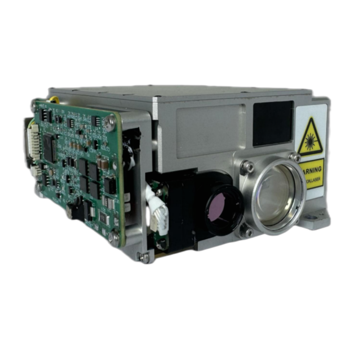

TECHNICAL SPECIFICATIONS
Control Function | ||
The laser target indicator can achieve the following control functions through the serial interface. | It has the laser ranging function. During ranging, distance data and status information are output once for each pulse. It can respond to the laser ranging command and can stop ranging at any time according to the stop command. It can perform cumulative counting of laser pulses. It can monitor the temperature and report the current temperature value to the system. It can set the target indication time, coding, and can output the selected settings. It can respond to the laser target indication command and perform target indication according to the set mode and coding. During laser target indication, the distance value and status information are output once for each pulse. It can perform laser target indication at the frequency set by external commands (in the state of laser coding irradiation, a software interface is reserved, supporting 8 kinds of fixed codings). Power-on Self-check: After powering on, it automatically conducts a self-check on relevant items. After the self-check is completed, it reports the self-check result and enters the standby state. Periodic Self-check: The laser ranging target indicator conducts periodic tests during the operation process. The periodic self-check does not affect the normal operation of the laser ranging target indicator. If a fault is detected, it reports the self-check report. Initiated Self-check: The system sends an initiated self-check signal. After the laser ranging target indicator receives this signal, it detects its functions and reports the inspection result. | |
Parameter Indicators | ||
Pump Source | Laser LD (Laser Diode) Pumping | |
Cooling Method | Passive cooling, no temperature control | |
Working Mode | Laser Ranging, Laser target indication | |
Operating Wavelength | 1064nm±3nm | |
Pulse Energy | ≥60 mJ | |
Laser Energy Stability | Within a single irradiation cycle, the pulse energy fluctuation does not exceed 10% of the average energy. | |
Pulse Width | ≥15ns±5ns | |
Beam Divergence Angle | ≤0.30 mrad | |
Stability of The Laser Optical Axis | ≤0.05mrad | |
Ranging performance | ||
Ranging Frequency | 1~20 Hz | |
Continuous Ranging Time | ≤300m | |
Maximum Ranging Distance | ≥12km(Visibility: 16 km, target reflectivity: 0.2, target size: 2.3 m × 2.3 m) | |
Ranging accuracy | ±1m. | |
Successful Ranging Rate | ≥98% | |
Continuous Laser Ranging Time | 5min(1Hz)/1min (5Hz)/20S(20hz) | |
Irradiation performance | ||
Precision of Laser Coding | ±1μs | |
Laser Irradiation Frequency | 1~20Hz | |
Laser Irradiation Distance | ≥6000m | |
Laser Target Designation Cycle | Short-period Irradiation Time: The duration of a single irradiation shall be no more than 17 seconds, with an interval of no less than 10 seconds between each irradiation, and it can perform continuous irradiation for 6 cycles.
Long-period Irradiation Time: The duration of a single irradiation shall be no more than 47 seconds. When restarting the irradiation, the interval shall be no less than 30 seconds, and it can perform continuous irradiation for 2 cycles. After completing a short-period or long-period irradiation, the time interval before starting the next irradiation should be no less than 30 minutes. | |
Laser Coding | ||
It complies with the requirements of MIL-STD-810G standard and has the expandable capability of user self-coding. | ||
It has the ability to receive external synchronous signals and encodes by controlling the laser beam emitting mode through external signals. | ||
Coding method: Precise frequency code (encoded with eight groups of pre-stored periodic codes). | ||
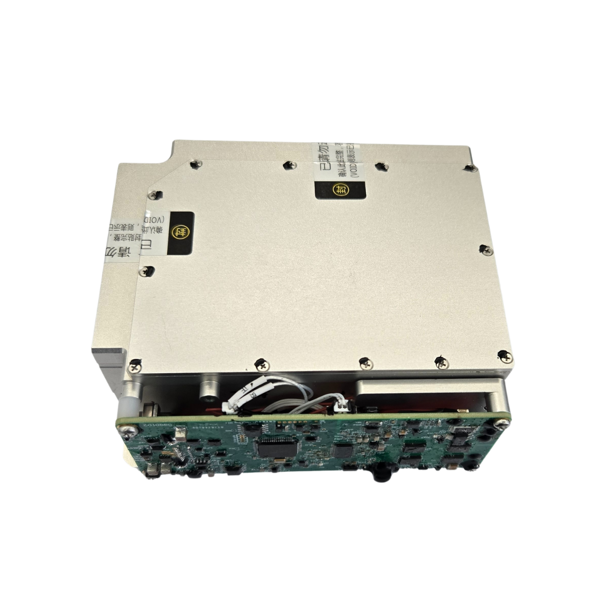
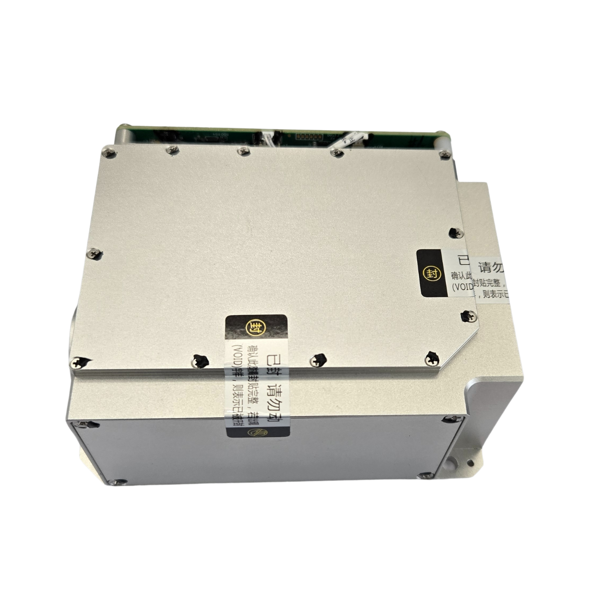
Dimensions and Weight | ||
External Dimension Envelope | ≤116mm×52mm×96mm | |
Weight | ≤680g | |
Degree of non-parallelism between the installation reference base and the optical axis | 0.5mrad | |
Input Power Supply Requirements | ||
During operation, the average power consumption is not more than 55W, and the peak power consumption is not more than 100W. | ||
The operating voltage range is from 20V ~ 28V. | ||
Three-proofing for Electrical Components | ||
After the circuit board is designed and debugged, it is coated with three-proofing paint for “three-proofing” treatment. | ||
Environmental adaptability requirements | ||
High Temperature | Operating temperature | ≤ +55°C |
Storage temperature range | ≥ -40°C | |
Low Temperature | Operating temperature | ≥ -40°C |
Storage temperature range | ≥ -45°C | |
Vibration Requirements | It can withstand the flight vibration as well as the impacts during takeoff and landing, and all equipment can withstand the environmental conditions of automobile transportation. The vibration is in the form of a swept frequency spectrum. From 15Hz to 33Hz, it is a sinusoidal vibration with equal displacement, and the displacement magnitude is 0.91mm; from 33Hz to 700Hz, it is a sinusoidal vibration with equal acceleration, and the acceleration is 2g. Vibrate in each of the three directions for 1 hour. Specimen Status: The product is placed on the test bench in the normal operating state for the impact test, and the product is powered on. After the impact test, the product should operate normally. | |
Shock Requirements | Vertical axial direction: ≥ 10g, Horizontal axis direction: ≥ 10g, Longitudinal axis direction: ≥ 10g; Post-peak sawtooth wave with a duration of 11ms. For the X, Y, and Z axes, in two directions of each axis, once for each direction, a total of 18 times. Specimen Status: The product is placed on the test bench in the normal use state for the shock test, and the product is powered on. After the shock test, the product should operate normally. | |