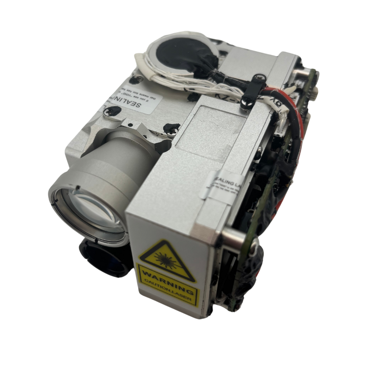
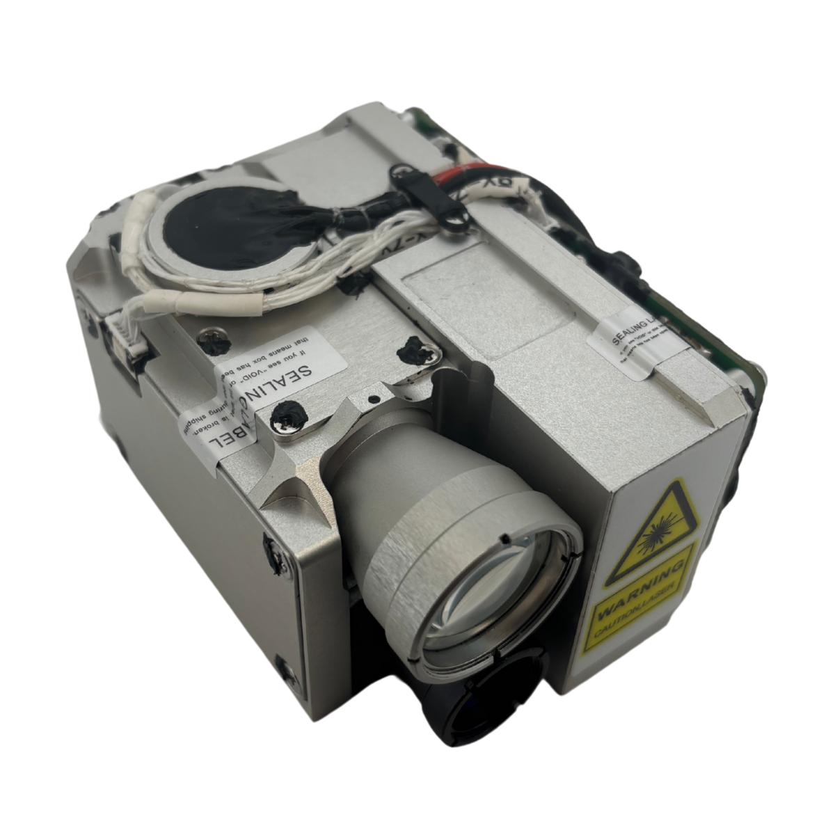
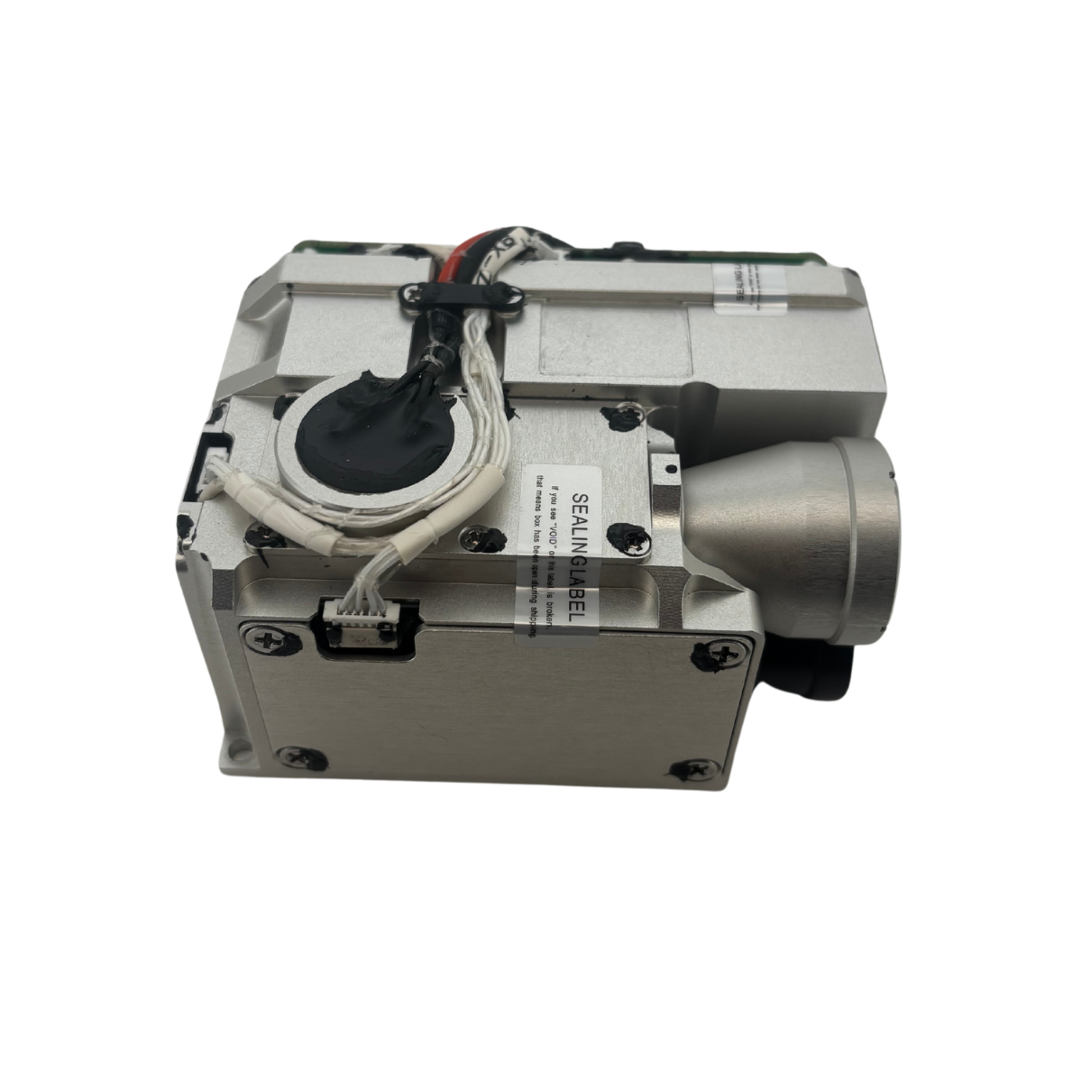
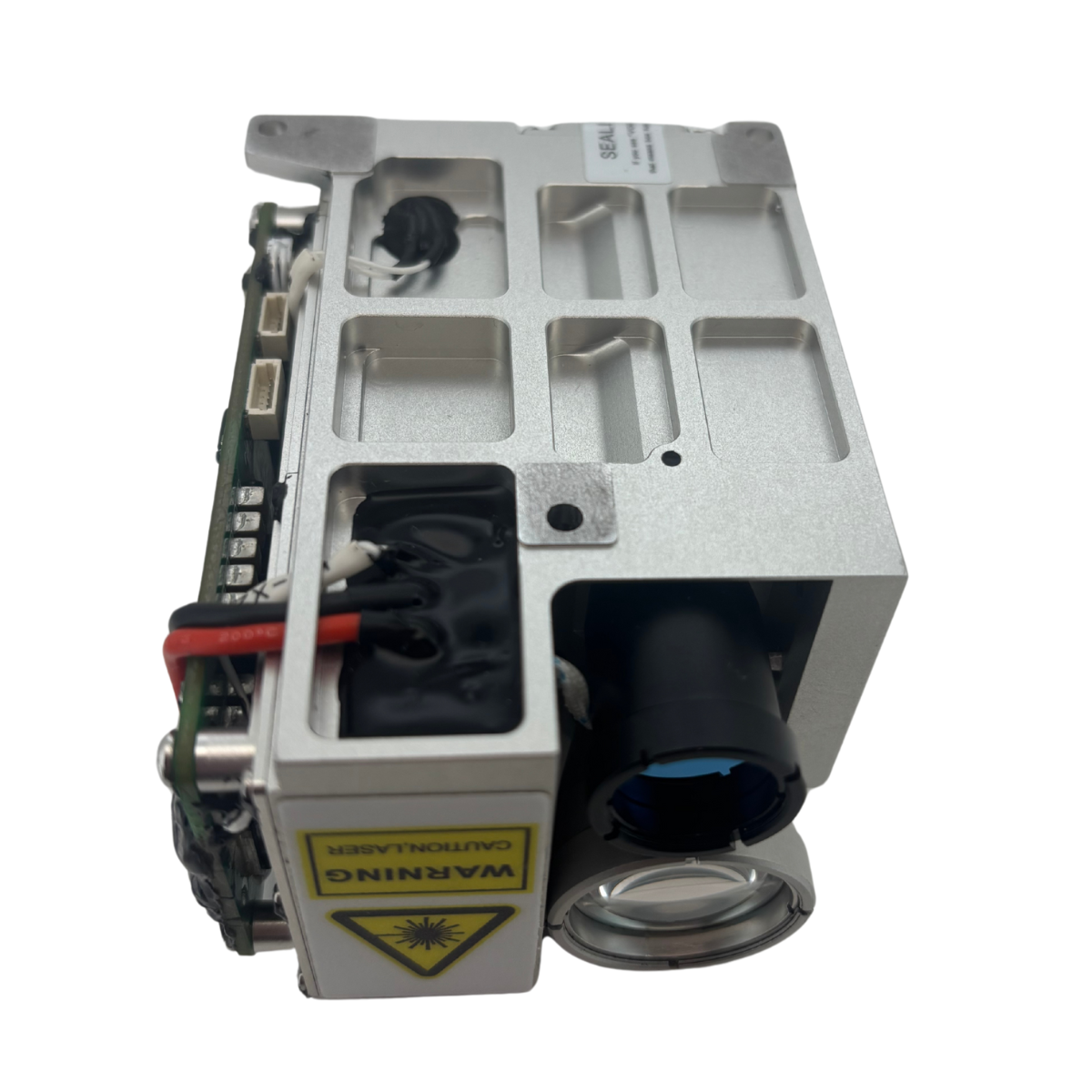
TECHNICAL SPECIFICATIONS
Control Function | ||
The laser target indicator can achieve the following control functions through the serial interface. | Respond to the laser ranging command and be able to stop the ranging operation at any time according to the stop command. Output distance data and status information once for each pulse during the ranging process. The ranging function has a range gating feature After starting continuous ranging, if no stop command is received, the ranging will automatically stop after 5 minutes (at a frequency of 1Hz) / 1 minute (at a frequency of 5Hz). It is possible to set the illumination mode and encoding Respond to the laser target indication command, perform target indication according to the set mode, encoding, and target, and be able to stop the target indication at any time according to the stop command. After starting the target indication, if no stop command is received, the target indication will automatically stop after one cycle. Output the distance value and status information once for each pulse during the laser target indication. Conduct power-on self-check and periodic self-check and output status information. Respond to the self-check activation command and output status information. Be able to report the cumulative number of laser pulses. | |
Parameter Indicators | ||
Pump Source | Laser LD (Laser Diode) Pumping | |
Cooling Method | Passive cooling, no temperature control | |
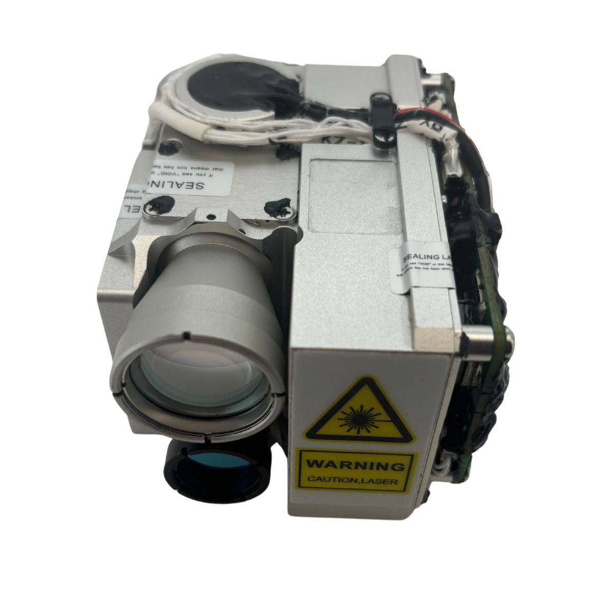
Working Mode | Ranging, target indication | |
Operating Wavelength | 1.064μm | |
Pulse Energy | ≥25mJ | |
Laser Energy Stability | Within one target indication cycle, the fluctuation of the single-pulse energy does not exceed 10% of the average energy (statistical data is collected 2 seconds after the light is emitted). | |
Pulse Width | ≥15ns±5ns | |
Beam Divergence Angle | ≤0.5mrad | |
Stability of The Laser Optical Axis | ≤0.05mrad | |
Ranging performance | ||
Ranging Frequency | 1~20Hz | |
Continuous Laser Ranging Time | 5min(1Hz)/1min (5Hz)/20S(20hz) | |
Continuous Ranging Time | ≤120m | |
Maximum Ranging Distance | ≥5000m(Visibility: 13.5 km, target reflectivity: 0.2, target size: 2.3 m × 2.3 m) | |
Ranging Accuracy | ±2m | |
Successful Ranging Rate | ≥98% | |
Ranging Logic | First and Last Targets | |
Irradiation performance | ||
precision of laser coding | ±1μs | |
Fundamental Frequency Of The Laser Target Designation Frequency | 20Hz | |
Laser Irradiation Distance | ≥2000m | |
Laser Target Designation Cycle | Short-cycle Target Designation: The duration of a single target designation shall not be more than 20 seconds, and the interval shall not be less than 30 seconds. Conduct continuous target designations for 8 cycles.
Long-period Target Indication: The duration of a single target indication is not more than 47 seconds. When starting the target indication again, the interval shall not be less than 30 seconds, and it is capable of continuous target indication for 2 cycles. | |
Laser Coding | ||
It complies with the requirements of MIL-STD-810G standard and has the expandable capability of user self-coding. | ||
It has the ability to receive external synchronous signals and encodes by controlling the laser beam emitting mode through external signals. | ||
Coding method: Precise frequency code (encoded with eight groups of pre-stored periodic codes). | ||
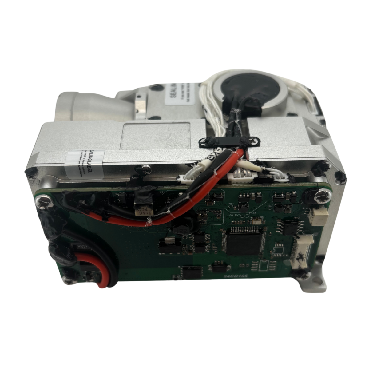
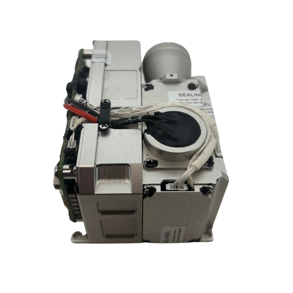
Dimensions and Weight | ||
External Dimension Envelope | ≤68mm×52mm×90mm | |
Weight | ≤380g | |
Input Power Supply Requirements | ||
During operation, the average power consumption is not more than 55W, and the peak power consumption is not more than 100W. | ||
The operating voltage range is from 20V ~ 28V. | ||
Three-proofing for Electrical Components | ||
After the circuit board is designed and debugged, it is coated with three-proofing paint for “three-proofing” treatment. | ||
Environmental adaptability requirements | ||
High Temperature | Operating temperature | ≤ +55°C |
Storage temperature range | ≥ -40°C | |
Low Temperature | Operating temperature | ≥ -40°C |
Storage temperature range | ≥ -45°C | |
Vibration Requirements | It can withstand the flight vibration as well as the impacts during takeoff and landing, and all equipment can withstand the environmental conditions of automobile transportation. The vibration is in the form of a swept frequency spectrum. From 15Hz to 33Hz, it is a sinusoidal vibration with equal displacement, and the displacement magnitude is 0.91mm; from 33Hz to 700Hz, it is a sinusoidal vibration with equal acceleration, and the acceleration is 2g. Vibrate in each of the three directions for 1 hour. Specimen Status: The product is placed on the test bench in the normal operating state for the impact test, and the product is powered on. After the impact test, the product should operate normally. | |
Shock Requirements | Vertical axial direction: ≥ 10g, Horizontal axis direction: ≥ 10g, Longitudinal axis direction: ≥ 10g; Post-peak sawtooth wave with a duration of 11ms. For the X, Y, and Z axes, in two directions of each axis, once for each direction, a total of 18 times. Specimen Status: The product is placed on the test bench in the normal use state for the shock test, and the product is powered on. After the shock test, the product should operate normally. | |